God Magnet
A pulsed-field station for materials experiments and field-coupling studies: a large working bore, a short high-field interval and a proposed repetition rate that puts heat removal and fatigue at the center of the design.
These values define the design point. Their simultaneous achievement, waveform, uniform volume and service life remain to be established. No completed Highfield apparatus or endurance test is asserted.
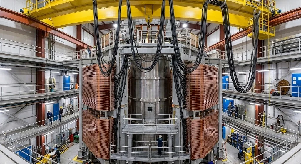
Bring the field to the experiment.
A high-field experiment needs more than a peak number. It needs a region in which the sample fits, a field history that can be measured, usable instrument paths and sufficient time between pulses to restore thermal and mechanical conditions. The station is intended to make those interfaces explicit.
The central sequence is simple: charge the energy store, establish current in the reinforced coil, acquire the sample response during the field interval, recover the usable magnetic energy and remove the heat before the next pulse. Every repetition revisits the same stress cycle.
FIGURE 2 — DESIGN-TARGET PROCESS CHAIN. Dashed connections identify proposed functional interfaces, not demonstrated internal supply.
At 20 Hz the start-to-start period is 50 ms. A 2 ms high-field interval occupies 4% of that period; current rise, decay, reversal and residual heat are additional waveform information, not permission to assume a 4% electrical duty factor.
A coil, its load path and its services.
The proposed pulse coil uses a copper-alloy conductor with structural reinforcement. Conductor alloy, reinforcement material, insulation, prestress and cooling arrangement remain design selections requiring property and fatigue data in the actual processed state. Cu–Ag is a candidate, not a measured material specification for this station.
Electrical boundary
Power converter, pulse store, switches, buswork, current measurement, energy-return path and independent dump path. Inductance, resistance and switching voltage follow from the eventual coil and waveform.
Mechanical boundary
Conductor, insulation, reinforcement, end restraints, mounts and fragment containment. The analysis must include radial loading, axial attraction, strain compatibility and repeated-cycle damage.
Thermal boundary
Conductor loss, eddy-current loss, joints, leads, switching and support heat loads. Cooling may use a selected low-temperature or warmer regime, but neither temperature nor refrigerator efficiency is assumed proven here.
Experimental boundary
Sample holder, pickup coil, feedthroughs, timing, digitization and electromagnetic compatibility. A nominal mechanical bore is larger than the sample space left after a cryostat and instrumentation are installed.
The external NHMFL 100 T design paper is instructive because its apparatus includes multiple electrical sections, reinforcement, cryogenic services and fragment containment. It is a source about that magnet, not a drawing or supplier specification for Highfield.
One hundred tesla carries a gigapascal load scale.
For a vacuum or approximately nonmagnetic region, the magnetic energy density and pressure scale are:
μ0 ≈ 4π × 10−7 H/m
At 100 T: pB ≈ 3.98 GPa
| FIELD | PRESSURE SCALE | READING THE RESULT |
|---|---|---|
| 1 T | 0.398 MPa | Field-energy scale, not a winding stress rating |
| 10 T | 39.8 MPa | Same numerical energy density in MJ/m³ |
| 20 T | 159 MPa | Four times the 10 T pressure scale |
| 100 T | 3.98 GPa | Twenty-five times the 20 T scale |
Calculated. The coil's actual stress is not equal to this pressure by definition. Maxwell stress is directional; winding forces follow J × B and the support geometry. Reinforcement thickness, current distribution, prestress, end forces and material interfaces determine the structural solution.
The magnetic-pressure technical note gives the derivation and limits. A short pulse does not eliminate peak force. It changes the time available for heating and mechanical response, and adds a fatigue problem when repeated.
No field-only failure threshold.
There is no universal rule that every 100 T coil must be destroyed, nor that a 50 T structure must fail. National MagLab reports nondestructive 100 T pulses. Its small-bore instrument does not establish the much larger working volume or 20 Hz target specified here.
The bore alone sets a substantial energy scale.
Use a transparent reference geometry before selecting a full coil: assume a uniform 100 T field over a cylinder 150 mm in diameter and 150 mm long. The diameter is the specified working bore; the effective axial length and uniform-field approximation are analysis assumptions, not a measured field map.
V ≈ 0.0026507 m³
Ubore ≈ B²V / (2μ0) ≈ 10.55 MJ
Calculated bore-region energy. The complete magnet stores energy in the windings and surrounding field as well. A full field solution, or measured inductance and current, is required for the total inventory and protection design. The bore estimate must not be used as a dump-resistor rating.
f Ubore ≈ 211 MW of cycled field energy
If recoverable-field-energy return η = 95% (assumed):
(1 − η) f Ubore ≈ 10.55 MW
The second result is an assumed recovery scenario applied only to the bore-energy estimate. It is not a measured wall-plug load. Resistive pulse losses, switching, leads, cooling and the rest of the field inventory still enter the energy balance. Recovering energy on field decay does not recover heat already deposited in a resistive winding.
| ASSUMED RETURN | UNRETURNED BORE ENERGY AT 20 HZ | EXCLUDED FROM THIS COLUMN |
|---|---|---|
| 0% | 211 MW | Total-coil energy and equipment losses |
| 90% | 21.1 MW | Total-coil energy and equipment losses |
| 95% | 10.55 MW | Total-coil energy and equipment losses |
| 99% | 2.11 MW | Total-coil energy and equipment losses |
A measured loss budget must integrate I²R over the complete current waveform and account for eddy currents, circuit losses and coolant heat removal without counting the same loss twice. If the eventual thermal plant cannot reject that load at the required temperatures, repetition rate, field, volume or conductor design must change.
At 20 Hz, ten million pulses correspond to 5.79 days of uninterrupted operation; one hundred million correspond to 57.9 days. These are calculated cycle-count conversions, not endurance claims. Neither number is an established lifetime for the proposed coil.
Real demonstrations define separate regimes.
| PRIMARY EVIDENCE | WHAT IT ESTABLISHES | WHAT IT DOES NOT ESTABLISH |
|---|---|---|
| MagLab 100 T multi-shot magnet | External nondestructive pulsed-field instrument; its description lists a 15 mm insert bore, with smaller usable sample environments. | 150 mm useful bore at 100 T, 20 Hz operation or Highfield hardware availability |
| MagLab 45 T DC hybrid | 33.5 T resistive insert with an 11.5 T outsert; 32 mm bore and listed 30 MW power | A universal requirement for superconductors between 20 and 50 T, or a low-power complete system |
| SPARC Toroidal Field Model Coil | Representative-scale high-field REBCO coil, approximately 20 T and 3 m in scale, reported by the project authors | The Iron Horse's proposed one-metre warm bore, operating envelope or commercial qualification |
| Hahn et al., 45.5 T test | A 14.4 T superconducting insert in a 31.1 T resistive background; published quench and post-mortem observations | Routine long-life operation at the peak test field, or a standalone 45.5 T low-power magnet |
These are external demonstrations and publications. They establish physical and engineering precedents within their reported apparatus and operating conditions. They do not establish internal suppliers or transfer an external laboratory's test history to a Highfield product.
Read the limitation with the record.
The 2019 Hahn paper presents the high-field result together with quench-voltage observations and post-mortem conductor analysis. Those source figures provide the starting point for assessing what peak field does and does not say about protection and reuse.
Measure the limiting cycle before building the station.
Begin with material and subcoil characterization, then a contained single-pulse arrangement. Increasing field, volume and repetition together would obscure the source of failure. The test sequence must identify conductor strain, irreversible change, thermal recovery and circuit behavior separately.
Isolated pulse circuit
Store → switch → subcoil → recovery or dump path. Record terminal voltage and current with a common time base.
Contained test article
Defined conductor and reinforcement geometry; strain and temperature instrumentation; independent field pickup.
Cooling measurement
Instrumented coolant boundaries or another validated calorimetric method; distinguish stored heat from rejected heat.
Acceptance record
Pre/post electrical checks, dimensional inspection and damage examination, then a justified repetition schedule.
| REQUIREMENT | PHYSICAL BASIS / EVIDENCE | GAP / ACCEPTANCE |
|---|---|---|
| Specified field in usable volume | Field load scale; external pulsed-field instrument | Field map and waveform in the actual instrumented bore |
| Reinforcement survives cycling | J × B load distribution; published nested-coil structural design | Processed-material properties, cyclic strain and inspected damage under the chosen pulse |
| 20 Hz thermal balance | Bore energy and explicit recovery sensitivity | Complete electrical loss accounting and measured heat rejection before sustained repetition |
| Protection and recovery | Stored magnetic energy; published quench evidence | Credible fault cases, dump path, insulation coordination and measured recovery fraction |
| Useful material experiment | Independently measured field and synchronized sample signal | Pickup rejection, calibration, repeatability and sample environment demonstrated together |
No maximum field, repetition rate or pulse count is accepted by a rendering or a materials brochure. The next deliverable is a traceable specimen and subcoil test record at stated conditions—not a declaration that the whole station has been validated.
Different tasks require different magnets.
Iso-Field
A specified 1 T precision-field platform. Bore volume, uniformity, stability and sample access define the task. MRI or spectroscopy applicability requires the complete measurement and safety system, not field strength alone.
Iron Horse
A specified 20 T REBCO industrial platform. The one-metre warm-bore envelope is a design requirement; current, strain, protection, refrigeration and duty remain to be resolved for that geometry.
H-LEV transport studies add air-gap geometry, guideway loads, controls and failure handling. A strong solenoid does not establish a maglev corridor. Fermat Logistics owns the transport integration; Phase Flash owns related thermal-process studies. Neither is presented as a qualified supplier.
Possible experimental interfaces with Stellar Furnace or Lorentz Aerospace remain research dependencies. A fusion or propulsion program must first specify why it needs this field, volume and waveform; the magnet does not prove the downstream mechanism.
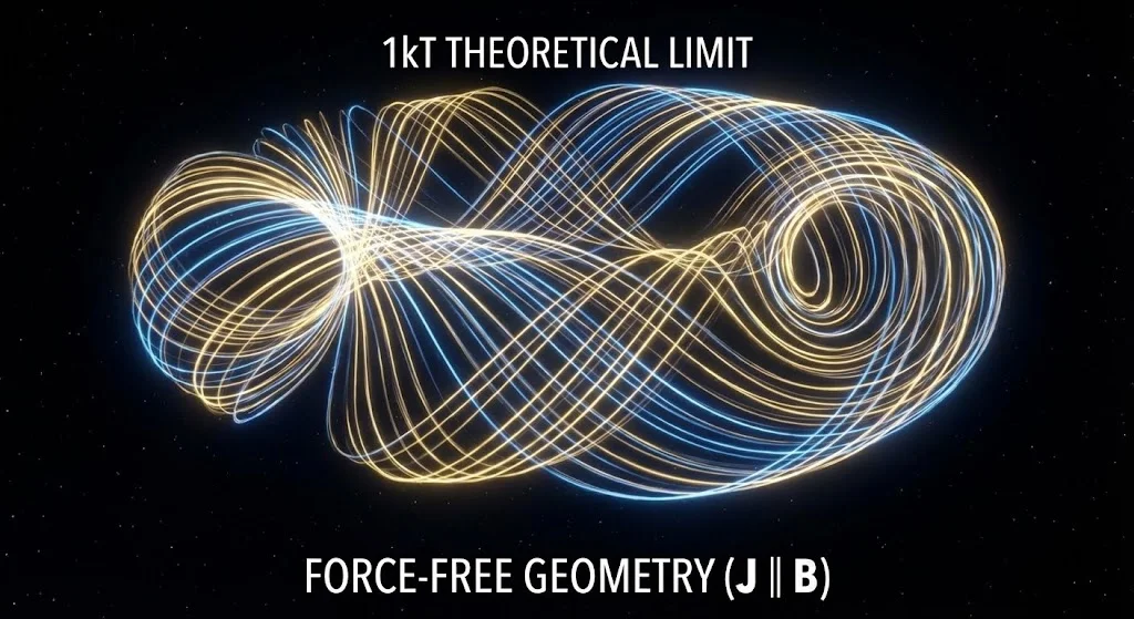
Retained configuration and research artwork



The sources actually used.
- Feynman, Leighton & Sands, Volume II, Chapter 27. Vacuum electromagnetic field energy.
- Bacon et al. (2002), The U.S. NHMFL 100 Tesla Multi-Shot Magnet. Design, analysis and fabrication progress; DOI 10.1109/TASC.2002.1018496.
- National MagLab, 100 T multi-shot apparatus. External nondestructive pulsed-field evidence and bore distinctions.
- National MagLab, 45 T DC hybrid. Resistive/superconducting architecture and listed power.
- Hahn et al. (2019), 45.5-tesla direct-current magnetic field. Measured peak field, quench and post-mortem evidence; DOI 10.1038/s41586-019-1293-1.
- Hartwig et al., The SPARC Toroidal Field Model Coil Program. Author preprint arXiv:2308.12301; representative-scale approximately 20 T REBCO demonstration.
Assumption receipt: specified 100 T peak, 150 mm bore diameter, 2 ms high-field interval and 20 Hz target; assumed 150 mm effective uniform-field length and selectable energy-return fraction. The pressure and energy values are analytical calculations. Coil geometry, conductor limits, complete energy, loss and endurance remain unresolved inputs.
Technical note
What magnetic pressure does a 10 T field produce? A bounded derivation with units and structural limits.
Read the note →Reference archive
Reviewed primary sources, their regimes and limitations. Unverified retained candidates remain separate.
Search reviewed references →